 |
|||
|
Page Title:
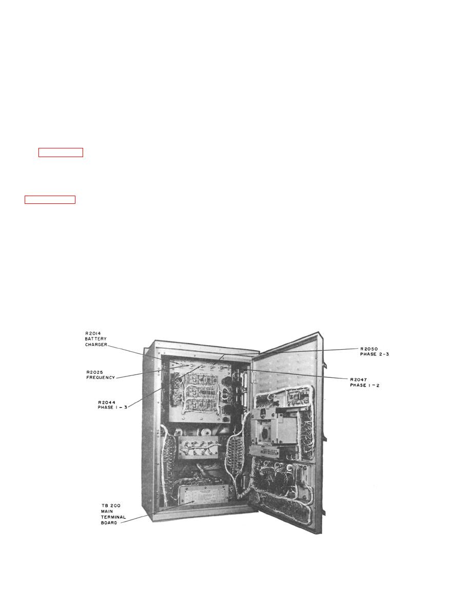
Figure 4-39.--Standby power supply, door open. |
|
||
| ||||||||||
|
|
 regulated rectifier is controlled with three
MK 19 MOD 3B GYROCOMPASS
silicon-controlled rectifiers. A dc filler is
SYSTEM
incorporated to smooth the output to the
battery .
The Mk 19 Mod 3B gyrocompass system is
identical to the Mk 19 Mod 3A system with the
Two sensing circuits consisting of several
exception of a few changes. The Mk 19 Mod 3B
resistors and a battery charging voltage
system uses a static standby power supply
potentiometer are also included in the charger.
instead of a motor-generator standby supply.
These components automatically sense charging
This standby power supply is considerably more
current and voltage, and send a signal to the
reliable than the motor-generator type since the
battery charging regulator.
only moving parts are the three relays used in
the sensing circuits.
The battery charging regulator receives its
po w e r f r o m a se c o n d w y e - w o u n d se c o n dar y o f
Figure 4-39 is an open-door view of the 3B
the input transformer (a neutral is not used).
standby power supply. The unit supplies a
The output of the transformer is rectified to
highly reliable 3-phase, 400-Hz, 115-volt, line-to-
36 v olts dc. In the battery -charg ing reg ulator,
line power from a 3-phase, 400-Hz, 115-volt or
comparison is made between the sensing
from a 120-volt dc source. For explanation,
circuit output and the second transformer
figure 4-40 is divided into two sections: a battery
se c o n dar y o u tpu t in th e c o n tr o l w in din g s o f
charger and an inverter. The battery charger
the reactor in the regulated rectifier. In this
will be discussed first.
manner, the firing of the silicon-controlled
rectifiers of the regulated rectifier are
The input transformer is a delta-wye, 1 to 1
controlled. By controlling the tiring of the
voltage ratio supplying approximately 110 volts
silicon-control rectifiers, the output of the
ac line-to-line on the secondary and 64 volts ac
regulated rectifier is controlled.
line-to-neutral. The wye secondary is used to
take advantage of the neutral.
A relay is used to delay connection of the
batteries to the charger until rated output is
The input transformer supplies a 3-phase,
obtained.
full-wave rectification circuit. The firing of the
40.125
|
|
Privacy Statement - Press Release - Copyright Information. - Contact Us |
