 |
|||
|
Page Title:
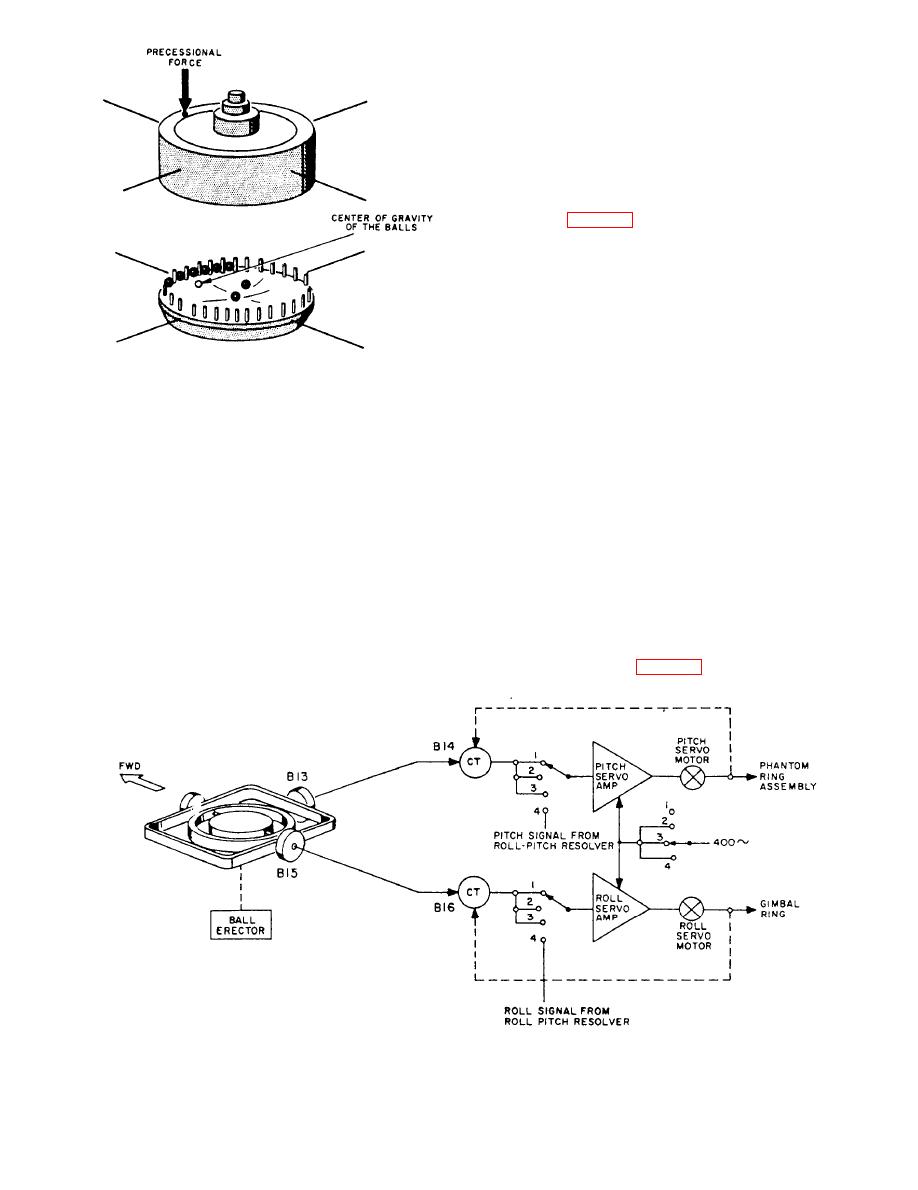
Figure 4-37.--Ball erector diagram. |
|
||
| ||||||||||
|
|
 uses a small stabilizer or start gyro mounted in its own
gimbal, which, when started, comes very quickly to a
vertical position, providing a fairly accurate level
reference for the roll-pitch phantom.
The stabilizer gyro rotor is the squirrel cage portion
of a 3-phase, 115-volt, 400-Hz induction motor, and
spins within the stator at 22,500 rpm in ball bearings that
are in the top and bottom of the gyro case. A ball erector
mechanism (fig. 4-37) is employed for maintaining the
gyro spin axis vertical. This mechanism consists of a flat
cylindrical enclosure suspended from the gyro case by
means of a ring that also serves as a bearing surface. It
is geared to the rotor shaft and rotates at 22 rpm about
an axis parallel to the gyro spin axis. When the gyro is
vertical, eight small balls are massed in the center of the
concave surface of a disk in the bottom cover. Eighteen
holder pins are equally spaced near the edge of the
concave disk. When the gyro tilts, the balls roll to the
The starting system functions to level the gyros and
lower side of the disk, where they are held loosely by
bring the meridian gyro to the meridian in as short a time
the holder pins and carried ahead, in the direction of
as possible. The starting sequence is accomplished with
rotation, toward the higher side. As each ball reaches a
a minimum number of manual operations by the
point where it can drop past the holder pin, it falls across
compass operator. The system includes a fast erect
the disk and resumes its cycle. The center of gravity of
system, a system control assembly, and part of the
the balls, so displaced, is at a point 90 from the low
control panel.
point, in the direction of rotation. Thus, a torque is
created that precesses the gyro in a clockwise direction
When the compass is to be started, the roll-pitch
viewed from above. The ball holder rotates in the same
phantom will be off its level position. A fast-erect system
direction and is easily observed because of its slow
is employed, which greatly reduces the time required to
speed.
bring the roll-pitch phantom (and therefore the gyros, as
they are caged to their vertical rings and the azimuth
Flat roll and pitch synchro transmitters are mounted
phantom during starting) to a level position. This system
on the stabilizer gyro (fig. 4-38). The output from the
4-34
|
|
Privacy Statement - Press Release - Copyright Information. - Contact Us |
