 |
|||
|
Page Title:
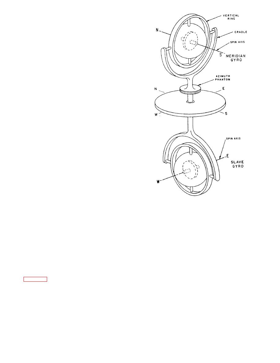
Figure 4-19.--Simplified diagram of the Mk 19 Mod 3A compass element. |
|
||
| ||||||||||
|
|
 and follow-up alarm are located on the control panel.
When a power failure occurs, the power available lamp
will go out. When a follow-up error occurs, the
follow-up alarm lamp will light up and an audible alarm
will sound.
SPERRY MK 19 MOD 3
GYROCOMPASS
SYSTEMS
The Sperry Mk 19 Mod 3 gyrocompass systems
furnish roll and pitch angle information as well as
heading information. This roll and pitch angle
information is used to stabilize gunmounts, missile
launchers, and other equipment that must remain level
with respect to the earth's surface for proper operation.
The Mk 19 Mod 3 gyrocompasses are used as the master
compass on Navy combatant ships. Some ships will
have two Mk 19 compasses installed; one will be used
as the master compass and the other as the backup
compass. There have been five modifications to the
original Sperry Mk 19 Mod 3 gyrocompass system since
it was first introduced. These five modifications will be
discussed in the following paragraphs.
MK 19 MOD 3A GYROCOMPASS
SYSTEM
The Mk 19 Mod 3A gyrocompass is a navigational
and fire control instrument with design features based
compass element.
on unusual requirements. The compass is designed to
operate in latitudes up to 80 with an accuracy of 0.1
in azimuth at sea. In addition, it accurately measures and
transmits angles of roll and pitch. These features
distinguish the Mk 19 Mod 3A from all other shipboard
gyrocompasses that preceded it.
An electric control system is used in the Mk 19 Mod
3A gyrocompass to make it seek and indicate true north
Design of the compass is based on the principle that
as well as the zenith. A gravity reference system is
two properly controlled horizontal gyros can, together,
furnish a stable reference for the measurement of ship's
electromagnetically to give the meridian gyro the
heading, roll, and pitch. Briefly, the basic unit consists
desired period and damping. Further, signals are
of two gyros placed with their spin axes as shown by
generated by the compass, which are used to stabilize
the entire sensitive element in roll and pitch, thereby
and is referred to as the north-seeking, or meridian, gyro.
Its spin axis is directed along a north-south line.
furnishing an indication of the zenith in terms of roll and
pitch data.
The lower gyro is a directional gyro with its spin
Both the meridian and slave gyros are enclosed in
axis slaved to the meridian gyro along an east-west line.
hermetically seated spheres and suspended in oil. The
It is referred to as the slave gyro and furnishes
indications of roll on north-sowb courses and pitch on
compass is compensated for northerly and easterly
east-west courses.
speed and acceleration, earth rate, constant torques, and
|
|
Privacy Statement - Press Release - Copyright Information. - Contact Us |
