 |
|||
|
|
|||
| ||||||||||
|
|
 The meter panel assembly contains the instru-
STATIC INVERTER
ments and controls necessary for the opration of the
The need for a highly dependable, static, 400-Hz
equipment.
power supply led to the development of the 4345A
The inverter module assembly contains a control
static inverter.
circuit +30-volt dc power supply, a drive circuit
+30-volt dc power supply, an input sensing circuit, a
The model 4345A static inverter delivers a closely
synchronizing subassembly, two variable pulse width
regulated 400-Hz, 3-phase, 120-volt output from a
generators, a frequency standard oscillator, a
250-volt dc source. Two single-phase static inverters
phase variable pulse width generator, two drive sub-
are operated with a controlled 90-degree phase
assemblies, a step change adjustment circuit, and two
difference. Pulse width modulation is used for control
silicon control rectifier power stages.
of the output voltage of each static inverter. The
The power stage assembly contains capacitors,
outputs of the two inverters are fed into two Scott
transformers, and filters associated with the power stage
of the inverters.
"T''-connected transformers to provide a 3-phase
output from a 2-phase input.
Maintenance
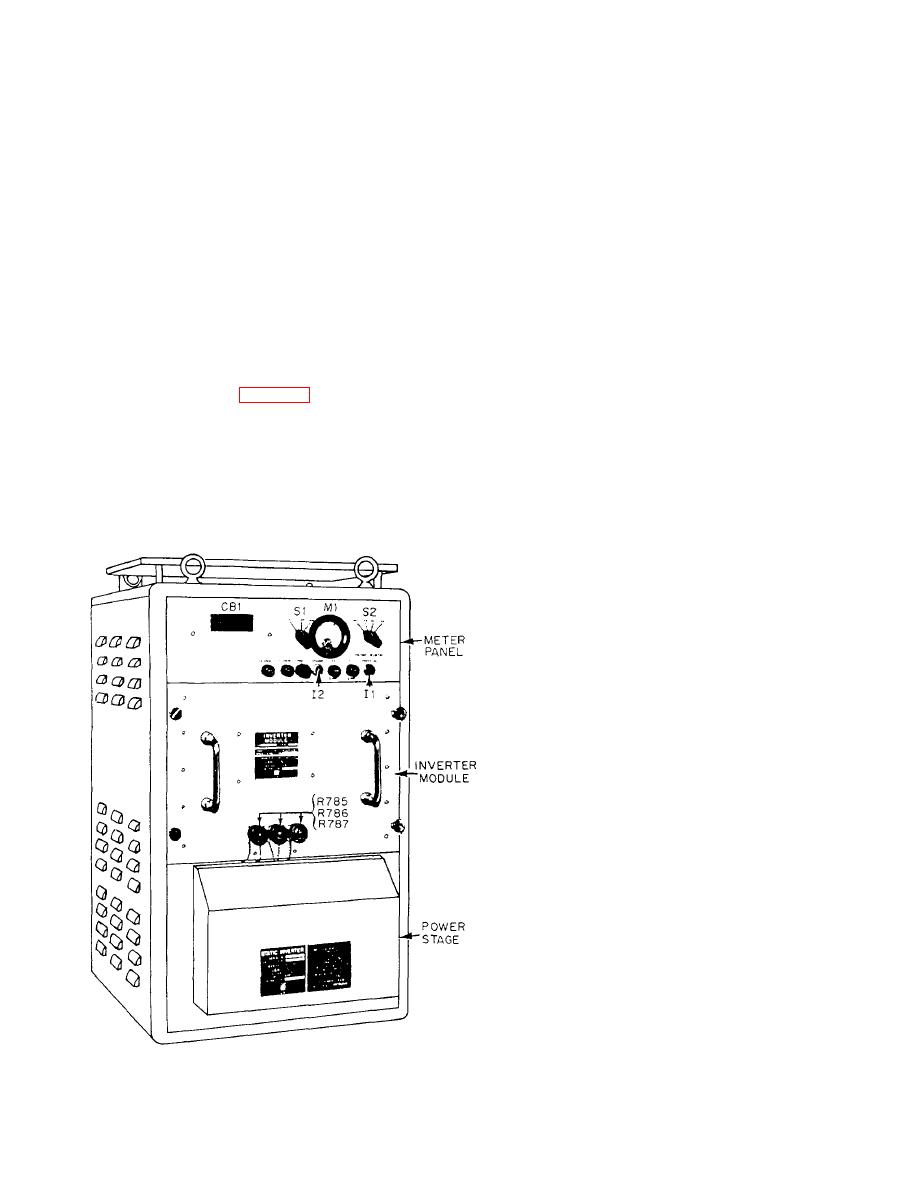
The 4345A static inverter is enclosed in an
aluminum cabinet (fig. 3-19), divided into three
Maintenance of the static inverter should normally
be limited to simple replacement with a new or service-
sections. These are the meter panel assembly, the
able module. This will ensure rapid restoration of
inverter module assembly, and the power stage
the inverter into service without risking dangers of
assembly. A resistor subassembly is located on the
handling high-test voltages,
back of the cabinet.
Complete familiarization with the theory of
operation must be obtained before troubleshooting is
attempted. Then follow the step-by-step procedures
outlined in the manufacturer's technical manual while
using the specified test equipment.
SUMMARY
In this chapter, we have discussed the ship's
service, emergency, and casualty PO wer distribution
systems found on board Navy ships and their impor-
tance in supplying power to the IC switchboards and
various IC systems.
We have discussed the main and local IC switch-
boards used to supply power to IC systems, the compo-
nents associated with the switchboards, and
switchboard maintenance. We have identified IC
systems by their classification and described a typical
IC test switchboard installed in IC shops for bench
testing IC equipment.
Now that you have finished this chapter, you should
have a better understanding of motor and generator
repair and troubleshooting.
The information covered in this chapter does
not include the necessary specifications or the specific
procedures for repair and maintenance of each piece of
equipment you will encounter. This information can
only be obtained from the appropriate NSTM and the
manufacturers' technical manuals.
|
|
Privacy Statement - Press Release - Copyright Information. - Contact Us |
