 |
|||
|
|
|||
| ||||||||||
|
|
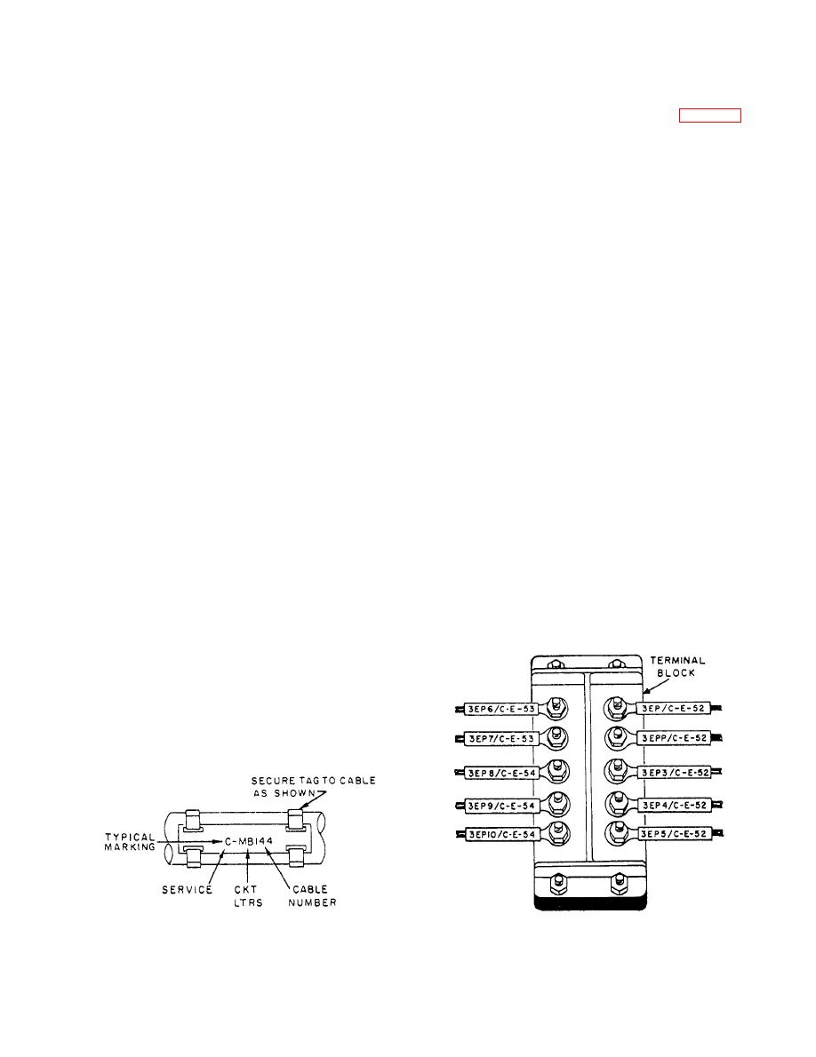 All IC terminals are identified by insulated
These cable designations include (1) the service letter,
sleeving that is stamped with the lead number and the
(2) the circuit letter(s), and (3) the cable number. The
cable number the lead belongs to.
SERVICE is denoted by the letter C, which is the
designation for all cables and circuits that comprise
The wire terminals 3EP and 3EPP (fig. 2-42),
the IC system in naval ships. Each circuit is
respectively, are the positive and negative supply
distinguished by a single letter or double letters. These
terminals from cable C-E-52, which emanates from
letters identify the cable as a part of one of the
the IC switchboard and leaves from cable C-E-53.
numerous IC circuits. If two or more circuits of the
same system are contained in a single cable, the
The wire terminals 3EP3, 3EP5, 3EP6, and 3EP8
number preceding the circuit letter or letters is
from cable C-E-52 are the positive terminals of
omitted. The cable number is the number of the cable
push-button stations 3, 5, 6, and 8, respectively. The
functions of these wires are found on the elementary
of the particular circuit.
and isometric drawings of the 3EP (protected E call)
A typical IC cable designation is C-MB144. The
circuit for your ship.
letter C denotes the service (the IC system). The letters
MB denote the circuit, engine-order system, which
Numbers following the circuit letter indicate a
serial number assigned for the station, followed by the
may actually include wires of circuits 1MB, 2MB,
section wire number designating the function of the
3MB, and so on. The number 144 denotes cable
circuit. On systems containing synchros, the numerals
number 144 of circuit MB.
1, 2, and 3 are used for the connections to secondary
Permanently installed ships' cables are tagged as
windings. Where more than one synchro is employed
close as practicable to each point of connection, on
in a single instrument, the numerals 4, 5, and 6 apply
both sides of decks, bulkheads, and other barriers.
to the second synchro, and 7, 8, and 9 to the third
Cables located within a single compartment in such a
synchro. For example, l-MB 14 should be interpreted
manner that they can be readily traced are not tagged.
as follows:
1--starboard circuit
TERMINAL MARKING
MB--engine-order system
In single-letter circuits and dc supply circuits, the
1--station number, such as pilot house
positive terminal is designated by a single letter, M.
4--connection to secondary windings of the No.
Similarly, an arbitrary polarity of single-phase ac
2 synchro receiver in the instrument
circuits is designated by a single letter, M (assumed
instantaneous positive). The other side (representing
the opposite polarity of both dc and ac circuits is
designated by double letters, MM.
Double-letter circuits have supply lead markings
assigned as for single-letter circuits, except that the
second letter of the negative is doubled; for example,
positive MB, negative MBB.
|
|
Privacy Statement - Press Release - Copyright Information. - Contact Us |
