 |
|||
|
Page Title:
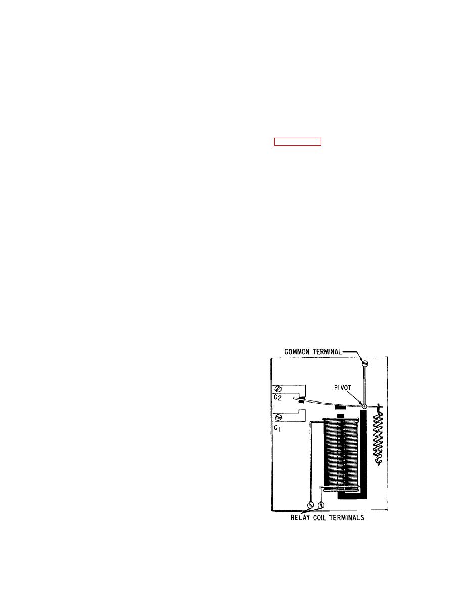
Figure 2-20.--Relay construction. |
|
||
| ||||||||||
|
|
 to the contacts. Use a burnishing tool for dressing
shorted turn acts as the secondary of a transformer, the
small light contacts.
primary of which is the relay operating coil. The
current in the shorted turn is out of phase with the
Clean burned copper contacts with fine sandpaper.
current of the operating coil because the copper ring
Do not use emery cloth. Badly burned contacts should
has low-inductive reactance. Thus, when the operating
be replaced. Always replace contacts in pairs, rather
coil flux is zero, the flux produced by the shorted coil
than replacing a single contact.
is different from zero, and the tendency of the relay to
Silver contacts require very little maintenance.
chatter is reduced.
Removal of the tarnish that forms on silver contacts
due to arcing is no longer recommended, as this
In general, a relay consists of a magnetic core and
blackened condition improves the operation of the
associated coil, contacts, springs, armature, and the
contacts.
mounting. Figure 2-20 illustrates the fundamental
construction of a relay. When the coil is energized, the
When replacing a switch, take great care in
flow of current through the coil creates a strong
tagging the leads to ensure proper replacement. Close
magnetic field that pulls the armature downward to
supervision and proper checkout by an electrical petty
contact C1, completing the circuit from the common
officer can ensure against personal injury and
terminal to C1. At the same time the circuit to contact
equipment damage.
C2 is opened.
Relays are classified according to their use as
RELAYS
control relays or power relays.
Relays are electrically operated switches. The
CONTROL RELAYS
operating coil can be connected in series with a supply
line to the load or shunted across the line.
Control relays are usually known simply as relays.
The coil design is influenced by the manner in
They are frequently used in the control of low-power
which the relay is used. When the relay is designed for
circuits or other relays, although they also have many
series connection, the coil is usually wound with a
other uses. Where multipole relays are used, several
fairly small number of turns of large wire because the
circuits may be controlled simultaneously. In
load current will be flowing through the winding.
automatic relaying circuits, a small electrical signal
When the relay is designed for shunt connection, the
coil is wound with a large number of turns of small
wire, which will increase the resistance and thus lower
the current through the coil.
Because the contacts of relays may open or close
when energized, they can be used as protective devices
or control devices or both simultaneously.
The basic difference between ac and dc relays lies
in the armature and magnet core construction. The
armature and magnet cores of an ac relay are made up
of laminations, and those of a dc relay are of solid
material. The use of laminations in an ac relay reduces
strap or ring (called a shorted turn) is placed near the
end of the pole piece of an ac relay to reduce chatter
during operation. Because the ac is going through a
peak, dropping to zero, going through a peak in the
opposite direction, and then dropping to zero again
during each complete cycle, the coil tends to release
the armature each time the current drops to zero and
attracts the armature each time it reaches a peak. The
|
|
Privacy Statement - Press Release - Copyright Information. - Contact Us |
